Carbon
Parts (Laser-cut)
Acrylic plate (top/bottom) 1/4" thick
Acrylic plate (middle) 1/8" thick


5 mm - Laid
Full Length - Laid
Videos
Initial Injection - Clogged
Initial Injection - Clogged [2]
Injection Sample 2 & 3 - Clog
Test Sample - Lay - Failed #1
Test Sample - Lay - #1
 |  |  |
|---|---|---|
 |  |  |
 |  |  |
 |  |  |
 |  |  |
 |  |

 Our fibers initially before cut. |  Epoxy in Syringe |  Epoxy in syringe |
|---|---|---|
 Pouring epoxy and carbon fiber into syringe. |  Mixing it. |  Initial injection test = clogging |
 Initial injection test = clogging |  Full Length Fiber Dog Bone Layup |  Full Length Fiber Dog Bone Layup |
 Full Length Fiber Dog Bone Layup |  Full Length Fiber Dog Bone Layup | 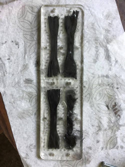 Full Length Fiber Dog Bone Layup |
 Full Length Fiber Dog Bone Layup |  Varying Lengths Carbon Fiber layup |  Varying Lengths Carbon Fiber layup |
 Varying Lengths Carbon Fiber layup |  Varying Lengths Carbon Fiber layup |  Varying Lengths Carbon Fiber layup |
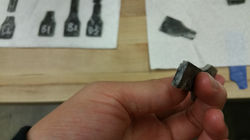
 Taking out the dog-bones from the acrylic mold. |  Threedog-bones before sanding. |  Before processing |
 Three full length fibers next to the mold it came from. Had to break apart a layer of the mold. |  Three prepped dog-bones |  Three prepped dog-bones |
All of the dog-bones |
[Final Experiment- 4/23/17]
Results and Discussion
When we injected the carbon with resin into the mold, we saw that the resin flowed very quickly to the tip and initially was only ejecting resin. Then a bundle of aligned fibers would start to flow out followed by a region of resin. This pattern alternated.
As a result we ended up just laying the fibers enriched with epoxy into the mold channels and took off our top mold layer. Pictures of our process are shown above. We also sprayed pam oil onto the mold to act as a mold release. We let the dog-bone pieces rest over night to cure as it takes 24 hours to fully cure. We then proceeded to break open the top mold by using a hammer and chisel. The oil we did add allowed the mold to release once we got excess epoxy and some of the acrylic out of the way. After we got the samples out, we sanded it under water and got rid of excess fibers to try to get a consistent thickness. Sanding under water allows us to safely sand as the residue gets trapped in the water.
Some pictures during our injection and layup of epoxy, sample retrieval and sample testing and displayed below.
TENSILE TEST RESULTS & OBSERVATIONS:
We made 3 samples for each fiber length so that we could get a better data and consistency. Especially with the layup method we performed, a lot of the samples varied with respect to width and thickness and even had some air pockets or defect. Once we got our 14 samples out of the mold, we then recorded the widths and thickness of each sample at 3 evenly spaced out points between the two tabs on either end. This is so we could find an approximate due to inconsistencies in the sample's thickness and width due to uneven sanding, human error and excess resin when performing the layup. We also calculated the standard deviation and error and uncertainty due to our processes.
Note: Density of the carbon fiber we used was: 0.12374 g/in^2 based on a cut sample that was 3" x 4.5" sheet of twill weave carbon fiber.
Because there were very many variables that could have contributed to error, we focused mainly on caliper measurement error and the number of samples. As such, the degree of freedom is the # of samples -1. So for most cases this was 2. For the epoxy samples, there was one degree of freedom. For a caliper there was a 5% uncertainty.
-
t_0.05, 2 = 2.92
-
t_0.05, 1 = 6.314
-
Source: Mechanical Measurements 6th Ed. Beckwith, Table 3.5
To find the uncertainty, which is the ± of the value given above, we do:
Uncertainty (95%) = (t_0.05,(n1-1)) x (std. dev.) / sqrt(n2)
Where n1 is the number of samples and n2 is the number of measurements made.
More on error and uncertainty can be found in the next section in white.
When we took these samples to the Instron machine to do tensile tests, we noticed that the peak force that was applied before fracture (which happened quite quick due to the brittleness of carbon fiber reinforced plastic) at 10 mm/min was (based on approximation):
Full Length Fiber [A] : 7000 N
15 mm Fiber [B]: 1000 N
5 & 10 mm Fiber [C] & [D]: ~ 800 N
Epoxy [1&2]: 200 N (although it stretched for around 12 mm due to an absence of carbon fiber and the elastic nature of plastics)
Using: and the raw data, we can find the stress plot. Then to find the yield stress, we would find the 0.2% elongation point. The numbers, averaged with error is plotted below.
Raw Data: https://drive.google.com/drive/folders/0Bw4Kgrdc2ywJZVdpQjI0Q0VqQ2M?usp=sharing
OBSERVATIONS:
Tensile Test:
-
Full fiber parts broke at the end sections, likely due to:
- The carbon is not straight at the ends like in the middle, so it is actually weaker at the wider section, which illustrates how braiding lower the strength of CFRP.
-
Could potentially be solved by adding metal plates to it for grips
-
Due to the anisotropic nature of composite, a flat strip with metal epoxied at both ends is more suitable.
-
Measured failure load was still significantly larger than the resin and carbon mixes
-
The line of fracture of full length CF is perpendicular to the direction of fiber at the neck
-
Instron grips shattering the part, since it is designed to grip into metal dog bones
-
Pure resin sample was highly elastic, adding the carbon pieces made it significantly more brittle and strong
-
Air bubble added from the stirring might have made the matrix more brittle. A process is needed to remove air bubble.
-
-
Perhaps a ratio between manufacturability and fiber length where longer fibers = more difficult to manufacture as a homogeneous mixture. The less homogeneous the mixture is, the more likely it would break at resin 'pockets' between the fibers
-
Long fiber tend to separate from resin
-
-
Fibers that did not fail at an imperfection failed at resin 'pockets'
We did notice that (especially for the epoxy test samples, there were bubbles that formed either from the air or oil. In addition, we assume that our injection and layup methods weren't standardized as that would require many more weeks of testing and a lot more resources that we did not have available. As such, there were many inconsistencies and errors with our methods. We believe that one result of this is that C samples, which had 10 mm long fibers (and were a little murky and white) could be a result of inadequate mixing and the presence of many small air bubbles. This could be because we didn't heat up the mixture to get rid of the bubbles (although this might've started to harden or cure the epoxy) or didn't use a shaker or mix well enough to get rid of the bubbles.
PRECISION VS. ACCURACY:
-
Our data appeared to be affected by the nature of the mixture used and our application methods, failing at either an area with imperfections (i.e. air bubbles, improperly filled areas) or resin ‘pockets’, where there is a much higher resin to carbon ratio than the surrounding area.
-
Our data may be biased due to the way the mixtures were formed, and how the air pockets formed in the parts. Because of this, the data likely does not portray what we initially intended. The measured failure loads are likely lower than the actual failure load of a better mixed sample. The degree of ‘good sample mixing’ cannot be evaluated after the samples are already tested. Mixing levels can only be quantified by machinery with minimal human error.
-
This means that, the statistical uncertainty may not include the actual strength of our part even within a 99% confidence interval, since uncertainties do not account for bias or measurement inaccuracies. However, the uncertainty range can still give valuable data by giving a range to check how far the measurements are from the ‘expected’ results described in other tests (mostly from papers, etc.).
-
Many of our uncertainties are very low, rounding to zero. This means that out measurements are likely very precise. However, this does not mean that they are accurate.
CONCLUSION:
We concluded that because there was not enough time and the scope of this experiment would become too broad, we would be focusing on the strength to fiber length and comparing to existing models. From what we can tell, full length fibers had almost 10 times the amount of yield stress than all of the shortened cut fibers. However, all the cut fibers were pretty close to each other in terms of strength and were all brittle. When there was no carbon fiber present, it became a lot more elastic and ductile. As a result, in terms of short length fibers, orientation of the fibers plays a much more important role or so we assume, but due to a lack of time and resources, was not able to research it. In addition, there were many errors and mistakes in our methods that could be fixed and would reduce the amount of error in our sample, but a lot of the samples were pretty consistent with one another. Another thing we noticed was for our full length fiber samples, they failed at the edges where the sample was clamped on due to a lower volume fraction concentration of fibers and due to the fibers going off at a slight angle, weakening it.

Existing Model
Looking at existing models from past research or models, we discovered Markforged which 3-D prints with carbon fiber, nylon or onyx. From their data, we observe that mixing short fiber into plastic improves small percentages in yield stress but lowers ultimate stress and makes it much more brittle at ultimate stress (less elongation before breaking). These are things we also noticed in our tests. The epoxy alone was very elastic and ductile, and stretched a lot before fracturing, even when it was half the thickness of the other samples. But when carbon fiber strands were added, it makes the plastic brittle even without air bubbles.
LINKS:
Markforged Material Data Sheet: https://markforged.com/landing/material-data-sheet/
[File]: https://drive.google.com/file/d/0B7BWjo4u3kFWSkRzbDVPRzhVQzA/view?usp=sharing